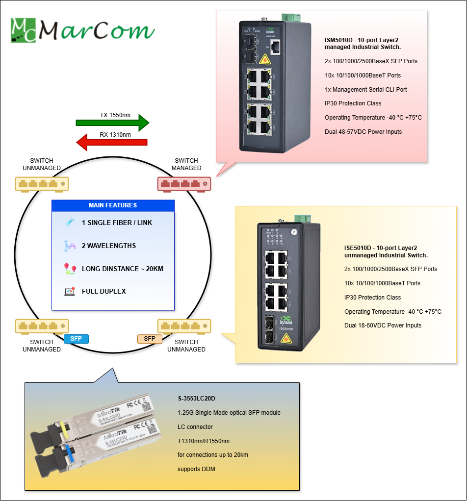
In industrial automation networks, reliability and operational continuity are crucial. The star topology, common in traditional IT environments, presents a single point of failure (the aggregation switch). To overcome this limitation, fiber optic ring topologies are often used, providing essential link redundancy for critical applications.
The use of industrial DIN Rail switches, such as those offered by brands specializing in industrial networking, is the standard for these implementations, thanks to their robustness, resistance to harsh environments, and easy integration into electrical cabinets.
Fiber Ring: General Overview
Key Components
To implement a redundant fiber ring, the choice of switch is fundamental:
- Managed Switch (Ring Manager):
- This is the critical element. The Managed switch must support an industry-specific ring redundancy protocol, such as MRP (Media Redundancy Protocol), RSTP (Rapid Spanning Tree Protocol), or a manufacturer’s proprietary protocol (e.g., P-Ring, Turbo Ring, etc.).
- It is configured as the Ring Manager (or Root), dynamically managing the opening and closing of the redundant link to prevent network loops.
- Switch A Manager (Managed o Unmanaged):
- The other switches in the ring can also be Managed (configured as Clients or Client Nodes) to provide advanced diagnostic and management capabilities. Alternatively, Unmanaged switches may be used if compatible ring protocols are employed, or if they are positioned in a daisy-chain configuration outside of the main backbone ring.
How Ring Topology Works
In a ring topology, each switch is connected to its neighbor such that the first and last switches in the chain are connected to each other, closing the loop.
Fiber optics are preferred over copper in this context for two primary reasons:
- Immunity to Interference: Essential in industrial environments with high levels of electromagnetic interference (EMI) generated by motors and heavy machinery.
- Extended Distance: Allows for the connection of switches located hundreds or thousands of meters apart.
The Principle of Redundancy
Un anello non gestito creerebbe un loop di rete, causando un broadcast storm e il blocco della rete. Per questo motivo, il protocollo di ridondanza deve:
An unmanaged ring would create a network loop, causing a broadcast storm and a total network collapse. For this reason, the redundancy protocol must perform the following:
- Normal State: Maintain one link (the 'backup link') in a blocked state to prevent the loop. Data traffic follows a primary path through the ring.
- Failover State: If the primary link is interrupted (e.g., a fiber break), the Manager/Root switch detects the failure and immediately unblocks the backup link.
- Reconfiguration Time: Advanced industrial protocols (such as P-Ring or MRP) ensure a very fast reconfiguration time, often under 20–50 milliseconds (ms), providing near-instantaneous recovery of communication.
Advantages of a Fiber Optic Ring Network
| Advantage | Description |
| Redundancy | The main advantage. A failure at any point in the ring does not interrupt the network; traffic is rerouted within a few milliseconds. |
| Low Latency | Fiber optics guarantee high transmission speeds and minimal latency, which are essential for real-time control data. |
| Cabling Simplicity | It requires simpler point-to-point cabling compared to a star topology, where cabling must return to a central point. |
| Scalability | Easy expansion by adding new switches as 'nodes' between two existing switches in the ring. |
| Industrial Robustness | DIN Rail switches are designed to operate in extreme conditions (temperature, vibrations, humidity), ensuring the longevity of the infrastructure. |
Creating a fiber optic ring using managed industrial DIN Rail switches is the most effective method for building a highly available and resilient network backbone for industrial automation and control.
The Bi-Directional Revolution: SFP BX for Long-Distance Fiber Rings
Modern networking demands increasing efficiency, especially regarding long-distance fiber optic links. For architectures such as ring topologies or point-to-point connections extending up to 20 km, traditional duplex SFP (Small Form-factor Pluggable) transceivers—which require two fibers—can become costly and burdensome in terms of cabling.
The solution to this challenge is represented by BX (Bi-Directional) SFP transceivers. These leverage single-mode fiber to optimize infrastructure, effectively halving fiber usage while maintaining high-speed, full-duplex communication.
The Core of the Technology: BiDi (BX) SFPs
A standard SFP requires two single-mode fiber (SMF) strands for a full-duplex connection: one for the transmit (TX) data stream and one for the receive (RX) data stream.
BiDi (Bi-Directional) SFP modules, commercially identified as BX, completely redefine this architecture. They are designed to operate over a single fiber strand (Simplex), allowing for the simultaneous transmission and reception of data over the same cable
The Essence of the BX Type
The key to this efficiency is WDM (Wavelength Division Multiplexing) technology, which utilizes two distinct, non-interfering light wavelengths to separate data streams in both directions:
- Transmission (TX) and Reception (RX) occur on different wavelengths.
- An internal optical filter (diplexer) within the module separates the incoming light from the outgoing light.
The Mandatory Pair
For communication to function, BiDi modules must always be installed in complementary pairs at both ends of the link:
| SFP Module | Transmits (TX) | Receives (RX) | Esempio di Codice |
| Side A (Upstream) | 1310 nm | 1550 nm | 1000BASE-BX10-U |
| Side B (Downstream) | 1550 nm | 1310 nm | 1000BASE-BX10-D |
Note: The most common wavelength for the 'Upstream' signal is 1310 nm, and for the 'Downstream' signal is 1550 nm, or vice versa, depending on the manufacturer.
Application in Long-Distance Rings (Up to 20 km)
A defining characteristic of SFP BX modules is that they are almost exclusively designed for Single-Mode Fiber (SMF). SMF is the only practical choice for network links exceeding 300 meters, easily meeting the 20 km (or greater) specifications required for Metropolitan Area Networks (MANs) or extended distribution rings
Strategic Advantages
- Cost Reduction: The primary benefit is a 50% saving on fiber infrastructure. In metropolitan rings or data centers where cabling is expensive, this results in a significant reduction in deployment and maintenance costs..
- Simplified Cabling: ewer fibers to manage and track reduces the likelihood of connection errors (a single fiber cannot be swapped or inverted).
- Space Efficiency: Utilizing a single fiber within a bundle or conduit increases overall cable density—a crucial advantage in congested environments.
Key Technical Specifications
When selecting a BX SFP for a 20 km ring, it is critical to ensure that the technical specifications are correct:
- Standard: Typically 1000BASE-BX10, 1000BASE-BX20, or 1000BASE-BX40, where the number indicates the supported distance (10, 20, or 40 km). For a 20 km span, the BX20 model is the ideal choice.
- Fiber: Single-Mode Fiber (SMF) is mandatory, often identified as OS1 or OS2.
- Connctor: The module utilizes a simple LC Simples connector.
- Optical Power(TX/RX): Power and sensitivity specifications must be suitable to cover the planned 20 km distance, ensuring a sufficient optical budget to account for signal attenuation.
In conclusion, BX-type SFPs represent a powerful and cost-effective solution for long-distance fiber networks, enabling the construction of robust, future-proof full-duplex infrastructures with half the cabling.
Discover these products on our online shop:
- ISM5012D Managed Industrial Gigabit Ethernet Switches with 8 Eth ports and 4 SFP ports
- ISE5010D
Unmanaged Industrial Gigabit Ethernet Switches with 8 Eth ports and 2 SFP ports
- S-3553LC20D Two SFP (1.25G) Module kit, single mode